Abstract
High speed steels have been known for about century, during which time there have been many developments to keep pace with increasing demands on properties and with advances in basic metallurgical understanding. So far, it has been possible to meet all challenges and after period of uncertainly in the early 1980’s, there appears to be resurgence in the importance of materials.
High-speed tools steels can be hardened and can maintain the hardness in service temperatures as high as 540 °C (1004°F), making them very useful in high-speed machinery. Typical applications are end mills, drills, lathe tools, planar tools, punches, reamers, routers, taps, saws, broaches, chasers, and hobs.
The specialty of this material and its application as cutting tool is very important in engineering field. So, some information about this material is trying to find out to improve the properties of this material that was also used in university of Malaya high-speed machinery at faculty of engineering.
In this Grouping project, we already have done some test on this material for it Mechanical properties, microstructure analysis (microanalysis) and the chemical analysis to determine the composition of the material.
The discussion between our project supervisor and us is to try to find out the process that is needed to do to improve the properties. This is because sometimes the tool is become failed in wear.
The comparison from the composition and hardness value of the sample that we have in experiment with the value readily available from manufacturer and from hand book was used to determine the type of this material.
Hopefully the discussion, conclusion and some recommendation from this project can be used to improve the uses of the cutting tools in University of Malaya.
Acknowledgement
We are very grateful to those who have helped in the preparation of this group project by discussion, provision of information and materials, which is also one of the courses in my studies in material engineering. To get an extra information in this project, we are the group member of ZUH 2 also used some references from a lot of books as our guide.
We are personally grateful to Dr. Zainul Huda as our group supervisor. Under his supervision this project finally can be done as we want even though it is not perfect at all. The information, advice, literature from him is very important for this project.
We are also want to say very thankful to our lab assistant Mr. Kohr Kim Choon at Metallurgy lab and Mr. Ismail at SEM lab for all single thing they help us in doing testing on this specimen.
We are also grateful to our entire group members; Nor Asikin binti Awang, Nasyrina binti Nasir, Nik Amiruddin Siru Bin Che Mustaffa and Rosmaini Firdaus. Co-operation from them is also very important in this project on our way to do all analysis, discussion, conclusion and presentation. Actually, all of them are a good group member.
Content
Page
1) Literature review
1.1) High Speed Steel Grades and Chemical composition
2) Methodology
2.1) Introduction of project methodology
2.2) Phase I: Hardness test and mechanical properties
2.2.1) Test 1: Rockwell Hardness Test
2.2.2) Test II: Vickers Hardness Test
2.3) Phase II : Chemical Analysis / Composition Analysis
2.4) Phase III: Microstructure analysis/ metallographic
3) Result and Discussion of testing / analysis
3.1) Result of Hardness test and mechanical properties
3.2) Result of Chemical Analysis / Composition Analysis
3.3) Result of Microstructure analysis/ metallographic
4) Conclusion and recommendation
5) References
6) Appendix
1) Literature review
High speed steel takes its name from its capacity to retain a high level of hardness when cutting metals at high speed. It is also appropriately named in view of more recent applications such as bearing for aircraft jet engines and for space-vehicle component. The important factor is that the steel can be hardened to level up to 1000 HV or 65 – 70 HRC, and that no appreciable softening takes place until temperature in the region of 600OC are reached.
High Speed Steel generally contains large amounts of alloys such as molybdenum, chromium, tungsten, vanadium, and cobalt with sufficient carbon to provide excess alloy carbides in the final heat treated structure. Maximum hardness is attained through secondary hardening after tempering. Aside from its hardness, one of the most important characteristics of high speed steel is its ability to retain this high degree of hardness at elevated temperature.
1.1) High Speed Steel Grades and chemical compositions
|
Grade |
Chemical Composition (Average Value in %) |
Standards |
----------Applications---------- |
|||||||
|
C |
Cr |
Mo |
V |
W |
Co |
BOHLER |
AISI |
BS |
|
|
|
IT1 |
0.75 |
4.1 |
- |
1.1 |
18.0 |
- |
S 200 |
T1 |
BT 1 |
Turning, Planing and slotting tools, taps, twist drills, threading dies, profile cutting tools, broaching tools, reamers. |
|
IT4 |
0.75 |
4.3 |
0.65 |
1.1 |
18.0 |
5.0 |
S 305 |
T4 |
BT 4 |
Turning, planing and milling tools, in particular for roughing work. |
|
IT15 |
1.50 |
4.5 |
- |
5.0 |
12.5 |
5.0 |
S 308 |
T15 |
BT 15 |
Turning tools for finishing a precision-cutting work. Where max. abrasion resistance and hardness retention and red hardness is required. |
The influence of alloying elements
on steel properties:
Carbon: Forms carbides, increases wear resistance,
responsible for the basic matrix hardness.
Tungsten & Molybdenum:
Improves red hardness, retention of hardness and high temperature strength,
forms special carbides of great hardness.
Vanadium: Forms special carbides of supreme hardness,
increases high temperature wear resistance, retention of hardness and high
temperature strength.
Chromium: Promotes depth hardening, produces readily soluble carbides.
Cobalt: Improves red hardness and retention of hardness.
Aluminum: Improves retention of hardness and red hardness
2) Methodology
2.1) Introduction of project methodology
In this project, there are three important test already have done. It is the hardness test, Microanalysis, and chemical analysis to determine the exact value of the sample that we have.
In the beginning of this project, all of us don’t know about the grade, hardness value, microstructure constituent and the composition of the sample. We just have given a bar of sample and need to do some test of hardness test, micro analysis and chemical analysis.
In this project, there are three important test already have done. It is the hardness test, Microanalysis, and chemical analysis to determine the exact value of the sample that we have.
The sample is a tool bit from the turning machine in faculty of engineering university Malaya workshop. The sample manufacturer is Miranda tools Co. and the physical dimension is 8 mm x 8 mm x 100 mm.
In the beginning of this project, all of us don’t know about the grade, hardness value, microstructure constituent and the composition of the sample. Our supervisor just gave a bar of sample and need to do some test of hardness test, microanalysis and chemical analysis.
For the first step of this project, we have done the hardness test by using the Rockwell and Vickers hardness-testing machine. The test is done at the Metrology lab at block Q faculty of engineering UM and assisted by Mr. Kohr Kim Choon. Thanks to him for helping us to do this analysis.
Our Second test is to do the chemical analysis to determine the composition of the sample and also at the same time the microanalysis (Not too good image can be achieve because of the machine can’t give a sharp microstructure figure). To do all of this analysis, we are using the scanning Electron microscope. The model is Philips XL 40 EDAX Energy Dispersive X – Ray Spectrometer (EDS). In this lab work, Mr. Ismail helped us, which is the lab assistant at SEM lab level 2 block L. Thanks to him for helping us to do this analysis.
Finally, the Microstructure analysis is also done at the same lab and also assisted by Mr. Kohr Kim Choon. This test is to do surface preparation and etching procedure. We also need to use optical microscope to determine the structure of materials by Microscopic examinations (Optical Microscopy or Microanalysis).
The details report of this entire test was prepared in the next section of this report. Some discussion and conclusion is already done with a lot of help from our project supervisor, Dr Zainul Huda. Some references was used as the comparison to determine the grade of this sample and to find the treatment to improve it against failure.
2.2) Phase I: Hardness test and mechanical properties
Hardness
test is the most important test to determine the properties of the high speed
steel. Actually, as we know hardness is the property of a material that
enables it to resist plastic deformation, usually by penetration. However, the
term hardness may also refer to resistance to bending, scratching, abrasion or
cutting. Hardness is not an intrinsic material property dictated by precise
definitions in terms of fundamental units of mass, length and time. A hardness
property value is the result of a defined measurement procedure.
The
above relative hardness tests are limited in practical use and do not provide
accurate numeric data or scales particularly for modern day metals and
materials. The usual method to achieve a hardness value is to measure the depth
or area of an indentation left by an indenter of a specific shape, with a
specific force applied for a specific time. There are three principal standard
test methods for expressing the relationship between hardness and the size of
the impression, these being Brinell, Vickers, and Rockwell. For practical and
calibration reasons, each of these methods is divided into a range of scales,
defined by a combination of applied load and indenter geometry.
2.2.1) Test 1: Rockwell Hardness Test
The Rockwell hardness test method consists of indenting the test material with a diamond cone or hardened steel ball indenter. The indenter is forced into the test material under a preliminary minor load F0 (Fig. 1) usually 10 kgf. When equilibrium has been reached, an indicating device, which follows the movements of the indenter and so responds to changes in depth of penetration of the indenter, is set to a datum position. While the preliminary minor load is still applied an additional major load is applied with resulting increase in penetration. When equilibrium has again been reach, the additional major load is removed but the preliminary minor load is still maintained. Removal of the additional major load allows a partial recovery, so reducing the depth of penetration. The permanent increase in depth of penetration, resulting from the application and removal of the additional major load is used to calculate the Rockwell hardness number.
|
HR = E - e |
F0 = preliminary
minor load in kgf
F1 = additional major load in kgf
F = total load in kgf
e = permanent increase in depth of penetration due to major load F1
measured in units of 0.002 mm
E = a constant depending on form of indenter: 100 units for diamond indenter,
130 units for steel ball indenter
HR = Rockwell hardness number
D = diameter of steel ball

Fig. 1.Rockwell Principle
Advantages of the Rockwell hardness method include the direct Rockwell hardness number readout and rapid testing time. Disadvantages include many arbitrary non-related scales and possible effects from the specimen support anvil.

Figure 2: Rockwell hardness tester at metallographic lab in faculty of engineering,
University of Malaya
2.2.2) Test II: Vickers Hardness Test
The Vickers hardness test method consists of indenting the test material with a diamond indenter, in the form of a right pyramid with a square base and an angle of 136 degrees between opposite faces subjected to a load of 1 to 100 kgf. The full load is normally applied for10 to 15 seconds. The two diagonals of the indentation left in the surface of the material after removal of the load are measured using a microscope and their average calculated. The area of the sloping surface of the indentation is calculated. The Vickers hardness is the quotient obtained by dividing the kgf load by the square mm area of indentation.

F= Load in kgf
d = Arithmetic mean of the two diagonals, d1 and d2 in mm
HV = Vickers hardness
|
|
When the mean diagonal
of the indentation has been determined the Vickers hardness may be calculated
from the formula, but is more convenient to use conversion tables. The Vickers
hardness should be reported like 800 HV/10, which means a Vickers hardness of
800, was obtained using a 10 kgf force. Several different loading settings give
practically identical hardness numbers on uniform material, which is much
better than the arbitrary changing of scale with the other hardness testing
methods.
The advantages of the Vickers hardness test are that extremely accurate readings can be taken, and just one type of indenter is used for all types of metals and surface treatments. Although thoroughly adaptable and very precise for testing the softest and hardest of materials, under varying loads, the Vickers machine is a floor standing unit that is more expensive than the Brinell or Rockwell machines.
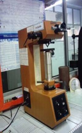
Figure 3:Vickers hardness testing machine at metallographic lab
2.3) Phase II: Chemical Analysis / Composition Analysis
Chemical analysis or composition analysis is needed to recognize the composition of the alloying element for the mechanical properties determination. Next to secondary electrons and backscattered electrons, the characteristic x-rays that are produced by the interaction of an electron beam with a sample are perhaps the most widely used signals in an SEM.
X-rays result from the incoming electrons knocking inner shell electrons out of atoms in the sample. As outer electrons drop into the vacancy, they are obliged to dispose of the excess energy, often as an x-ray photon. Since each element has its own unique set of energy levels, the emitted photons are indicative of the element that produced them. Analyzers are then used to characterize the x-ray photons for their energy (or wavelength) and abundance to determine the chemistry of sample.
In this project, we also have already done the chemical analysis of the sample to determine the composition and the surface microstructure. To do all of this analysis, we are using the scanning Electron microscope. The model is Philips XL 40 EDAX Energy Dispersive X – Ray Spectrometer (EDS)

Figure 4: The Philips XL 40 EDAX Energy dispersive X – ray spectrometer at SEM lab, Faculty of Engineering University Malaya.
The description of the machine:
|
Model: |
Philips XL-40 |
|
Type: |
Scanning Electron Microscope |
|
Resolution: |
3nm @ 3okV and 15nm @ 1kV |
|
Monitor: |
2 unit 17” monitor display |
|
Computer |
Pentium PC, |
|
Operating System |
MS Windows 3.11 |
|
Software |
FEI XL Control, FEI XL Metrology |
|
Data Recording: |
Polaroid Camera, video printer, Frame store extension to eight images |
Equipment overview:
Energy Dispersive X-ray
Spectroscopy (EDS)
This
technique is also sometimes referred to as EDXA (energy dispersive x-ray
analysis) or EDAX (energy dispersive analysis of x-rays). EDS or EDXA are
preferred since EDAX has been adopted as a trademark and name by one of the
suppliers of EDS systems.
EDS operates by using a crystal of silicon or germanium to detect the x-rays. Each photon generates multiple electron-hole pairs equal in total energy to the energy of the photon (each pair has a fixed energy determined by the crystal). A voltage is applied to the crystal to separate the electrons and holes so that the charges appear as a small step-change in voltage. Pre-amplifiers and amplifiers process the signal and pass it to a multi channel analyzer (analog-to-digital converter) so that the x-ray spectrum can eventually be displayed as a histogram of x-ray intensity as a function of energy. The detector crystal is kept under vacuum at liquid nitrogen temperatures. It thus requires a window of some kind to isolate it from the SEM chamber. Early windows were made out of beryllium, but severely attenuated x-rays from elements lighter than sodium. An improvement in materials has led to a generation of "thin-window" detectors which can pass x-rays down to and including boron. This is a great help when analyzing minerals (O) and organic compounds (C and O).
Procedure:
1) The sample is placed inside the microscope's vacuum column through an air-tight door.
2) After the air is pumped out of the column, an electron gun [at the top] emits a beam of high-energy electrons. This beam travels downward through a series of magnetic lenses designed to focus the electrons to a very fine spot.
3) The final image is built up from the number of electrons emitted from each spot on the sample.
2.4) Phase III: Microstructure analysis/ metallographic
As we all know in material science and engineering, there is a relation between the properties and microstructure of materials. Much has been written on the subject of the properties and testing of high speed steels, but it is still not true to say that after about century use of subject is not fully understood. There are many reasons for this. Some of the properties are related to the matrix and carbide phase, and thus the properties are very much related to structure. There is also general lack of understanding of the forces in cutting operation, and there is considerable diversity in the properties of the materials to be cut or worked. There is also inevitably some heterogeneity in the high-speed steel, on macro or micro-scale.
Procedure:
1) Specimen Surfaces preparation
The specimens need only be polished on pile cloth for removal of the oxygen film formed on the tested surface to be viewed under the microscope.
Fine polishing is often done using a water coolant and silicon carbide abrasive paper mounted on rotating disc. The two-wheel unit in the laboratory can be equipped with rough polishing wheel and a final polishing wheel. Wheel speed for final polishing has to be set at a second position (about 1150 rpm). A small stream of water is directed at the center of the rotating wheel
a) Rough polishing
This operation can be performed by means of different type sand paper. For rough polishing, an adhesive sand paper should be used as a covering for the rotating polishing wheels. During rough polishing the specimen is moved in a clockwise direction around the polishing wheel to insure equal metal removal from the entire surface by not allowing prolonged polishing in any one direction.
b)Final Polishing
Final polishing is very similar to that used for rough polishing. The abrasive particles used in final polishing are generally carried on a napped or short pile cloth such as billiard cloth or micro cloth. Most polishing cloths can be obtained cut to size and coated with an adhesive backing. The adhesive back eliminates the need for mechanical clamping.
CAUTION!
Be sure that you supply the rotating wheel with continuous flowing water. This step is taken to insure cool surface during polishing.
c) Etching of specimens
Polished metal specimens usually show no structural characteristics. Etching of the metal surface is done to make visible the crystalline structure of the metal and to produce optical contrast between the various constituents. Exposing the cleaned and polished specimen surface to suitable etching solution does etching. These etching reagents are powerful, hazard and must be handled with care. In this test we use the ethanol 2 %.
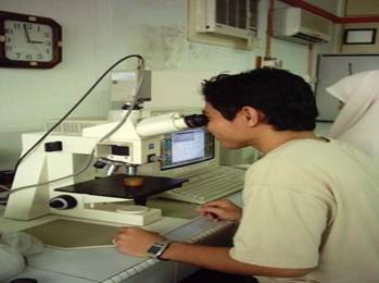
Figure 5: Microstructure imaging system at Metallurgy lab
3) Result and Discussion of testing / analysis
After all of the testing and analysis is done, the result was used to help us to determine the grade of sample. All of the information was important and comparing with the information from other textbooks does the determination process. The mechanical properties of the material now can be found out and the improvement of characteristics can be planning to get better materials.
3.1) Result of Hardness test
In this test, we just set up the Vickers and Rockwell hardness test. We trying to set up for the impact testing but we have some problem to make the “C” notch which is required for high speed steel impact test. Beside that, the size of specimen that we have is not a standard size for impact testing which is required 10 mm x 10mm x 100mm but our specimen dimension is 8 mm x 8 mm x 100 mm.
|
|
Vickers Hardness test |
Rockwell Hardness test ( HRC )
|
|
|
Diagonal |
VHN |
||
|
Reading 1 |
136 |
1003 |
66.2 |
|
Reading 2 |
130 |
1097 |
67.2 |
|
Reading 3 |
131 |
1081 |
67.0 |
|
Average |
132.33 |
|
66.8 |
Table 1 : Result of hardness test
3.2) Result of Chemical Analysis / Composition Analysis
Before we do this analysis, our lab assistant at the SEM lab, Mr. Ismail already says that we cannot get the exact composition of this sample because the equipment is not good enough to use for high-speed steel. The type of EDX machine that we use is the high vacuum type but we need the other type of EDX machine.
Anyway, we still trying to find out the composition, but the result of some composition are not correct when we do some discussion with Dr. Zainul Huda. The value from the textbooks is also not same as we get. Anyway, we still use the result for the other composition.
3.3) Result of Microstructure analysis/ metallographic

Figure 6 : Microstructure result of specimen ( High speed steel )
3.4) Discussion of testing / analysis
Actually, to determine the grade of this high-speed steel, we need or must know the exact composition of component in this specimen, but in this project we can’t get the exact composition. This is because the equipment, which can do a good chemical analysis for high-speed steel, is not in faculty of engineering UM.
To determine the grade of this material, a discussion with Dr. Zainul Huda was done. From the discussion, we decide to use the hardness value to determine the grade of materials.
As the result, we decide that the grade of this material is BT 15 because the hardness of this grade high-speed steel is the closest to our value of our Vickers hardness number, but we know this is not a good way to determine the grade. The actual composition of the BT 15 is shown is shown in appendix 1.
4) Conclusion and recommendation
4.1) Conclusion
Even though the result of chemical analysis is not too good, the assumption of the grade of materials is BT 15 is done regarding to the hardness value of specimen.
As conclusion, for this grade, the material is extremely hard and this is happen because of the high composition of vanadium weight percentage (value from appendix 1, not from test) but also tough. This grade of material is usually used for the tools forming, turning, milling and shaping. It is also use for cutting gas turbine alloys.
4.2) Recommendation
Some treatment will be done to improve the mechanical properties, but the most affective is the Crucible Particle Metallurgy (CPM) process. The fine structures that result from rapid solidification in the CPM process offer premium characteristics for both the manufacturers of cutting tools and their users. The more uniform distribution and the finer size of carbides in CPM steels are especially evident in comparisons with larger diameter bars of conventionally produced high speed steel, where carbide segregation is more of a problem. Thus, while the benefits pertain to cutters of all dimensions, they are more pronounced in larger tools.
There are four principal benefits of CPM high-speed steels for tool users;
a) The
primary benefit is the availability of higher alloy grades, which cannot be
manufactured by conventional steelmaking. These grades provide enhanced wear
resistance and heat resistance for cutting tool applications.
b) CPM increased toughness of CPM high speed steels not only provides
greater resistance to breakage (particularly valuable in intermittent cut
operations), but it also allows a tool to be hardened by 0.5 to 1.0 points
higher on the Rockwell C scale without sacrificing toughness. Both longer
tool life and higher cutting speeds can be realized.
c) CPM offers improved grind ability with no reduction in wear resistance of
the tool. This means reduced grinding-wheel wear.
Grinding can be done more quickly with less danger of damage to the cutter, and
it leaves an edge that produces a smoother finish on the work piece.
d) Fourth, the greater consistency in
heat treatment and uniformity of properties of CPM high-speed steels increases
the degree of predictability for scheduling tool changes. This factor is
particularly advantageous in multi-spindle machines, where a single cutter
failure affects several spindles and usually requires changing all cutters
(including some that may have a lot of life left) for the sake of prudence.
On our way to get the better high-speed steel to use in our workshop of engineering faculty, the selection of the high speed steel with the finer microstructures distribution is needed.
Finer Carbide Size and Distribution

Conventional HSS CPM
This illustration
shows the key metallurgical characteristics responsible for the successful
application of particle metallurgy products. Both microstructures are for
2" diameter AISI T15 - CPM on right and conventionally produced on the
left (500X, longitudinal cross section).
Note the very fine and uniformly dispersed carbide distribution in CPM steels compared to the segregated distribution and broad size range of the carbides in the conventional product. The finer carbide structure in CPM also results in finer grain size control.
The differences in micro structural control between CPM and
conventionally ingot-cast high alloy tool steels of the same composition can
have a decisively beneficial influence on the steel’s behavior in certain
tool manufacturing operations as well as on tool performance. Specifically, these
potential benefits include:
a) Better annealed machine ability
b) More consistent and safer heat treat response
c) Significantly improved grind ability
d) Good toughness characteristics
e) Larger size capability in full length bars
5) References
6) Appendix 1