“Material
Characterization and Engineering Of
Super-heater Tube
of Boilers”
(ZUH 78-A)
By:
Nik Amiruddin Siru Bin
Che Mustaffa
KEB 000041
Session 2004/2005

A graduation exercise for
Faculty of Engineering University of Malaya
In partial fulfillment of the requirement for the
Degree of Bachelor of Engineering,

Department of Mechanical Engineering,
University Of Malaya,
Kuala Lumpur.
DECLARATION
BY THE CANDIDATES
I, Nik Amiruddin
Siru Bin Che Mustaffa, hereby declare that except where due acknowledgement has
been made, the work presented in this thesis is my own, and has not been
submitted previously in whole or in part, to qualify for any other academic
award.
The content of this
graduation exercise is the result of the work I have been carrying out since
the official commencement date of the approved thesis project.
Full
Name: Nik Amiruddin Siru Bin Che Mustaffa
NRIC
No: 810904-03-5113
Metric
No: KEB 000041
ABSTRACT
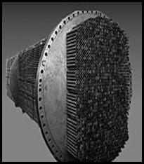
Super-heaters tubes are generally exposed to high
temperature and pressure particularly at tip sections where the flue gas
temperature may rise to more than 1000 ºC (Ray AK, Kumar P et al, 2002;
Ray AK, et al, 2003). With a steam temperature of 540ºC Inside the tube
the outer metal temperature may exceed 600 ºC. Tube materials may vary
from carbon steel to low Cr ferrite to austenitic stainless steel. Super heater
tubes under operating condition are very much prone to the formation of oxides
on both inner and outer layers. Initially the outer oxide layer is essentially
Fe304 type and inside the tube is a spinal-type oxide
containing steel alloying elements.
In
this graduation exercise, I have already have done some test on the specimen (a
length of super-heater of a boiler) for it Mechanical properties,
microstructure analysis (microanalysis) and the chemical analysis to determine
the composition of the material.
The
discussion between my research supervisor and me is to try to find out the
grade of the specimen that was given to me (according to ASME specification),
which is base on the mechanical properties, element composition and
microstructure distribution.
ASME
grade of the specimen is very important to studies on the application of this
tube in the boiler. The studies is including the suitable condition of the tube
to give a good services in boiler, the life of services before it fail and the
type of engineering failure take place.
Hopefully the discussion, conclusion and some recommendation from this
graduation exercise can be used to improve the knowledge in the super-heater
tube uses, and in the same time to maximize the efficiency of it operating
services in industries when boiler is needed.
ABSTRACT
Tiub Super-heaters biasanya terdedah kepada suhu
dan tekanan tinggi terutamanya pada bahagian permukaan tip dimana suhu gas
boleh mencecah sehingga 1000 ºC (Ray AK, Kumar P et al, 2002; Ray AK , et
al, 2003)., dengan suhu stim 540ºC di bahagian dalam dan 600 ºC
pada bahagian luaran logam tiub. Bahan yang digunakan sebagai tiub super-heater
adalah terdiri daripada pelbagai variasi logam samada dari keluli karbon rendah
hinggalah logam tahan-karat austenit. Keadaan operasi komponen ini didalam
pendidih mewujudkan keadaan dimana pembentukan oksida logam di kedua-dua
bahagian dalam dan luaran tiub berlaku. Kebiasaanya, pada bahagian luaran
selaput oksida logam ialah jenis Fe304 dan pada bahagian
dalam pula ialah jenis oksida-spinal yang mengandungi elemen pengaloian logam.
Dalam
penyediaan latihan ilmiah ini, saya telah menjalankan beberapa ujian keatas
spesimen (Tiub Super-heater daripada pendidih) untuk menguji sifat
mekanikal, analisis mirostruktur dan analisis kimia untuk mengenalpasti
komposisi elemen didalam spesimen.
Perbincangan
antara penasihat dan saya adalah untuk mengenalpasti gred sebenar tiub yang
telah diberikan kepada saya (Berdasarkan kepada standard ASME), yang mana ianya
adalah Berdasarkan kepada sifat mekanikal, komposisi elemen dan keadaan
mirostruktur.
Penentuan
gred ASME spesimen adalah amat penting bagi membantu kajian untuk menentukan
kesesuaian keadaan tiub ini paling sesuai digunakan sebagai tiub Super-heater
didalam pendidih dalam industri. Kajian ini merangkumi kajian mengenai
tahap tekanan dan suhu paling sesuai untuk tiub ini beroperasi dan menyentuh
sedikit mengenai jenis kegagalan kejuruteraan yang biasamnya terjadi dalam
industri.
Saya berharap dengan segala Perbincangan, kesimpulan dan cadangan
peningkatan sifat mekanikal daripada latihan ilmiah ini dapat dijadikan
platform yang kukuh dalam pemahaman dan pengetahuan mengenai tiub super-heater
dapat dipertingkatkan.
ACKNOWLEDGEMENT
Alhamdulillah, all
praise and glory to Allah, because with only through His mercy and help, this
graduation thesis project could be completed successfully.
I
feel very grateful to those who have helping me in the preparation of this
graduation exercise project by discussion, provision of information and
materials. Preparation of this research is as a partial
fulfillment of the requirement for the Degree of Bachelor of Engineering,
First of all, I would like to express
my truthful thankfulness to my beloved family, for their continuous spiritual
support and encouragement, as strength for me to complete this thesis project
success.
To Dr. Zainul Huda, I am very thankful
for his precious support, understanding, motivation and his expert guidance and
valuable advised to make this thesis fruitfully. Once again to Dr. Zainul
Huda, thank you very much!
In
this special space I also want to say very thankful to our lab assistant,
especially Mr. Kohr Kim Choon at Metallurgy lab and Mr. Zaman for every single
thing they helping me in the preparation guidance of specimen and testing on
this specimen.
I
also grateful to my entire lecturer, especially to my beloved head of
department, Prof. Madya Dr. Iskandar Idris Ya’acob and our thesis
co-coordinator, Dr. Ibrahim Henk Matselar for the guidance and help.
I also would like to express my
warmest gratitude to all my colleagues, Khairul Anuar, Abdul Kadir Majid,
Zalinor Zainuddin, Norhaslinda Binti Jamahar, Nasyrina Binti Nasir and all my
friends for their precious helps and contribution to this research project.
Last but not least, to the one and
only, Miza Binti Ahmad Zaidi, thank you so much for her endless helps
inspiration and supportive support throughout the accomplishment of this
thesis.
For
those that I do not mention here, but maybe indirectly a part of this research,
I also want to say thank you very much on every single thing that they are
helping me.
NIK AMIRUDDIN
SIRU
Department of
Material Engineering
University of Malaya
February 2005
TABLE OF
CONTENT
Page
Declaration by
the candidate
ii
Abstract iii
Abstract
translation v
Acknowledgement vii
Table of content ix
List of table xi
List of figure
xii
Chapter 1 Introduction
and objectives of research
1.1
Introduction 1
1.2 Objective
of research 2
Chapter 2 Literature
review
2.1
Boiler and its operation principal 3
2.1.1 Boiler classification 4
2.2
Engineering of super-heater tubes in boiler 7
2.2.1
Material engineering of super-heater tubes 8
2.2.2
Engineering design of super-heater tubes 16
Page
Chapter 3 Research
materials and characterization method
3.1
Research Material 18
3.1.1
Material physical dimension 18
3.1.2
Material application in industries 19
3.1.3
Material common specification 19
3.2
Methodology 21
3.2.1
Surface preparation of the sample 23
3.2.2
Spark Emission Spectrometer (SES) 29
3.2.3
Optical Microscopy 31
3.2.4
Vickers hardness test 34
Chapter 4 Result
and discussion
4.1 Result and discussion of
elemental / chemical analysis 38
4.2 Result and discussionof Hardness
testing 42
4.3 Result and discussion of Microstructural
analysis 43
Chapter 5:
Conclusion and Recommendation
5.1
Conclusion 48
5.2 Recommendation 49
References 51
Appendices 55
LIST OF TABLE
|
Table
no.
|
Table
Description
|
Page
|
|
Table
2.1
|
Table that
shows the various group of Martensitic steels due to the percentage of carbon
content and chromium.
|
11
|
|
Table
3.1
|
Shows the
grade, description of the steel, the type of the tube (either seamless or electric
resistant welded, ERW) and the uses of it
|
19
|
|
Table
4.1
|
Percentage of
major alloying element obtained from Spark Emission Spectrometer (SES)
|
38
|
|
Table
4.2
|
Result of hardness test
|
42
|
LIST OF
FIGURE
|
Figure no.
|
Figure
description
|
Page
|
|
Figure 2.1
|
Flow diagram
for a typical boiler plant
|
4
|
|
Figure 2.2
|
Example of a
low temperature and pressure fire tube boiler
|
6
|
|
Figure 2.3
|
Example of a low
temperature and pressure water tube boiler
|
6
|
|
Figure 2.4
|
Super-heater tube may varies
widely; (a) Stainless steel tube and (b) ERW boiler tube
|
16
|
|
Figure 2.5
|
various design of super-heater
tube
|
17
|
|
Figure 3.1
|
The photo of the specimen on
the (a) side and (b) cross- sectional view
|
18
|
|
Figure 3.2
|
Flow of material
characterization method
|
22
|
|
Figure 3.3
|
Imptech® 201 rotary
pregrinder machine at metallurgy lab
|
25
|
|
Figure 3.4
|
Polishing
machine
|
27
|
|
Figure 3.5
|
Shimadzu® Spark
Emission Spectrometer machine
|
30
|
|
Figure 3.6
|
Optical microscopy imaging
system at metallurgy lab
|
32
|
|
Figure 3.7
|
Vickers hardness determination
of diagonal
|
34
|
|
Figure 3.8
|
Vickers hardness testing machine at material science lab
|
36
|
|
Figure 4.1
|
Plot of
element composition percentage of each element from SES
|
39
|
|
Figure 4.2
|
The optical
micrograph of sample under various magnifications (a) 100X, (b) 200X, (c) 500X
and (d) 1000X
|
41
|
|
Figure 4.4
|
The influence
of grain size on yield strength in ferritic steel
|
49
|
CHAPTER 1: INTRODUCTION AND
OBJECTIVES OF RESEARCH
1.1 INTRODUCTION
This thesis project is a step of my studies in the field of
materials engineering in University of Malaya. The title is about the
“material characterization and engineering of super-heater tube of a
boiler”.
The
studies is including the studies on the basic knowledge of the boiler types and
its operation, the studies on the common steel types that was used as the
super-heater tubes and the engineering of it in the boiler and the most common
alloying element was used to improve the properties of the tubes.
The
studies on the latest design of the super-heater tubes also have been done in
this graduation exercise to make sure this research is more useful for the
industrial application.
The
core of this research is to do the material characterization technique on a
specimen (a length of super-heater tube of a boiler). The characterization is
including the studies on the Microstructural analysis using optical microscope,
the studies on the compositional analysis of the specimen that was done using
Spark Emission spectroscopy (SES) and the study on hardness value of the
sample.
1.2
OBJECTIVE OF RESEARCH
The
objective of my research is actually divided to three important parts; the
first part is to study on the basic principle of boiler operation and engineering
of super-heater tube as a component of a boiler (the needs of properties of
material to meet the requirement as super heater tube, which is operated at
high temperature and pressure).
My
second objective is to do the experimental work including mechanical testing
(hardness test), compositional or chemical analysis, and to do the
microstructural analysis.
The
third objective is to analyze all the data from the experimental work to
observe the properties of the material and suitability of it as steel that was
used as heat resistant steel in the high range of temperature operation
component in a boiler and give some recommendation to improve the properties of
the sample given.
CHAPTER 2: LITERATURE REVIEW
2.3
BOILER AND ITS OPERATION PRINCIPAL
A boiler is a closed vessel in which water under pressure is transformed
into steam by the application of heat. In the boiler furnace, the chemical
energy in the fuel is converted into heat, and it is the function of the boiler
to transfer this heat to the contained water in the most efficient manner. The
boiler should also be designed to generate high quality steam for plant use. A
flow diagram for a typical boiler plant is presented in Figure 2.1. The boiler
shows in the red colored elliptical mark.
A boiler must
be designed to absorb the maximum amount of heat released in the process of
combustion. This heat is transferred to the boiler water through radiation,
conduction and convection. The relative percentage of each is dependent upon the
type of boiler, the designed heat transfer surface and the fuels.

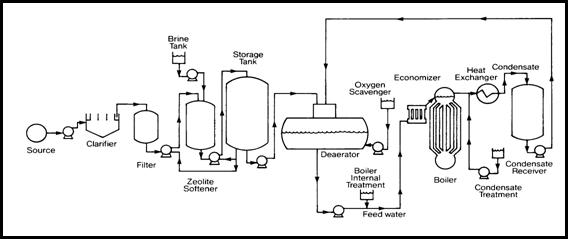
Figure
2.1: Flow diagram for a typical boiler plant (internet reference, 7/9/2004)
2.3.1
Boiler Classification
Boiler may be
classified on the basis of any of the following characteristics:
a)
Service duties. Boiler may be either stationary or
mobile. Stationary boiler serves for heating, central station, plant process
steam, and plant power steam. Portable boiler includes the locomotive type, and
miniature steam generator.
b)
Pressure. To provide safety, all insurable
stationary must be constructed in accordance with approved codes by American
Society of Mechanical Engineers: “Boiler and pressure vessel code”
(ASME boiler code).
i)
Low pressure steam boiler pressure (< 15 Psi).
ii)
Subcritical pressure – pressure < 3206 Psi and
temperature 750°F.
iii)
Supercritical pressure – operation above Subcritical
condition.
c)
Heat source. May be derived from:
i)
The combustion of fuel (solid, liquid or gaseous);
ii)
The hot waste gases of other chemical reaction;
iii)
The application of electrical energy;
iv)
The utilization of nuclear energy.
d)
Fuel. Boilers are often designated with respect its
fuel e.g.: coal, gas, oil, etc.
e)
Furnace position. The furnace is internally fired
if the furnace region is completely surrounded by water coolers surfaces. The
furnace is externally fired if the furnace is auxiliary to the boiler or built
under the boiler.
f)
Circulation. Majority of boilers operate with
natural circulation, some utilize force circulation.
g)
Tubes.
i)
Fire tube boilers are boilers with straight tubes
that are surrounded by water and through which the product of combustion
passes. See figure 2.2.
ii)
Water tube boilers are boilers which the tubes
themselves contain steam or water, the heating being applied to the outside
surface. (Abdul Rahim & Mohd Normarzuki, 2001). See figure 2.3.
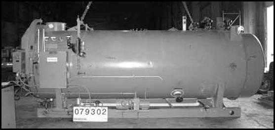
Figure 2.2: Example
of a low temperature and pressure fire tube boiler (internet reference,
1/2/2005)

Figure 2.3: Example
of a low temperature and pressure water tube boiler (internet reference,
1/2/2005)
2.4
ENGINEERING OF SUPER-HEATER TUBES IN BOILER
When we talk about the engineering of a super-heater tube, the things that
always crossed our mind is the design of the super-heater tube and the material
that suitable for the high temperature service
The conversion of thermal energy into mechanical or other form of energy is
more efficient the higher the operating temperature of the heat engine used.
This statement is reply very closed to the super-heater tube in the boiler. The
factor limiting the temperature actually used is the hot strength of the
materials of the super-heater tube is made. These are usually metals, employed
because of their high strength, their relative ease of fabrication into complex
shapes, and their resistance to brittle fracture under the mechanical or
thermal stress.
The basic criteria for metals suitable for structural uses at high
temperature are:
i.
High melting point or range (the metal must be solid to
retain shape)
ii.
Reasonable strength at temperature of service plus, in
some cases, light weight or high stiffness.
iii.
Ability to be fabricated to desired shapes.
iv.
Sufficient ductility at room temperatures and at high
operating temperatures to resist brittle fracture.
v.
Resistance to oxidation, inherent or attained by coatings.
2.4.1
Material engineering of super-heater tubes
To meet the requirement of the super-heater tubes as a pressure part in
the boiler, the material was made with core material like carbon and some
various alloying element such as chromium, nickel, molybdenum, manganese,
phosphorus, and sometimes with niobium and tantalum.
Each alloying
element has their own properties, and the properties of each element will be
discussed here. It is very interesting to discuss on five most important
alloying elements that is exist widely in super-heater tube of a boiler. The
influence of alloying elements on the properties:
a)
Chromium. Chromium has two attributes when alloyed
in steel.
First, it combines with carbon to form very hard
chromium carbides. These considerably increase the hardenability of the steel.
The chromium content varies from as low as 0.5% to about 5.0%, and it is often
found in conjunction with other carbide forming elements such as vanadium,
molybdenum, and tungsten
Second virtue of chromium is that it enhances corrosion
resistance and resistance to oxidation at temperature. Chromium alone in
quantities from 10% to 20% gives steel with very good corrosion resistance.
When over 7% Nickel is added to steel with 17% and more chromium and austenitic
steel is formed.
b)
Nickel. Nickel used as the alloying element in the
low alloy steel. Nickel is a ferrite strengthener and thus imparts the
toughness to steels, increasing the ductility without decreasing the tensile
properties. It also found that nickel also used as alloying element in
austenitic steel with the percentage of 8% to 10% nickel add to the 12%
to 18% chromium steels.
(Robert B. Ross, 1968).
c)
Molybdenum. Molybdenum and its alloys are
characterized by the ease of working and fabrication at room temperature with
excellent mechanical properties at elevated temperatures, but very poor
resistance to hot oxidation. Addition of small percentage of titanium and
zirconium increase the creep strength, and raise the temperature required to
remove cold work. The use of molybdenum and it alloys are now used for high
temperature part like super-heater tube commonly and extremely as parts in jet
engines and space rocket motors.
d)
Manganese. Widely used as an alloying element with
a considerable number of uses. The most common is a de-oxidizers and
de-sulphidizer in the manufacture of steel. Iron oxide and sulphide are brittle
refractory materials which tear the plastics during rolling or forging. With
manganese present, these are converted to manganese oxide and sulphide, both of
which are plastic during working temperature of steel.
e)
Vanadium. By far the largest use for vanadium is as
alloy in steel, where it combines with carbon to form stable carbides. Theses
are always dispersed and have considerable influence on the grain size of the
steel. It has also been shown that small quantities of vanadium inhibit the
tendency of chromium carbide to agglomerate. These properties have a
considerable effect on the ductility, and fatigue strength.
f)
Silicon. Silicon improves the resistance of the
alloy to attack by oxygen, air or hot oxidizing gases. It is used primarily for
the ‘heat-resisting’ alloys. Its action on the structure is similar
to that of chromium; it is a ferrite former that contracts the γ loop.
From this point of view its action is stronger than that of chromium. All that
has been said regarding chromium in this respect can be taken to apply to
silicon.
g)
Titanium and niobium. Universally used in
austenitic steel and play an essential role in them. They have an extremely
high affinity for carbon and thereby suppress the precipitation of chromium
carbide during slow cooling or prolonged holding at temperatures of the order
of 700°C, preventing the local chromium impoverishment which has such a
disastrous effect on corrosion resistance. Both elements are strong ferrite
formers. In austenitic steel, more-over, they can give rise to precipitation
phenomena which promote improved strength properties at high temperatures.
h)
Boron. Trace of boron addition improved the creep
and rupture strength of heat resisting alloys. (L. Colombier & J. Hochmann,
1965).
By using the effect of various elements on corrosion, and creep
resistance, a wide range of grades can be obtained to meet various service
requirement of the super-heater tube of the boiler; they fall into common three
group of:
a)
Martensitic steels. Martensitic steel can be
divided into four groups:
Table 2.1:
Table that shows the various group of Martensitic steels due to the percentage
of carbon content and chromium.
|
|
Carbon
content, %
|
Chromium
content,%
|
|
Group I
|
Below 0.15
|
12 – 14
|
|
Group II
|
0.20 –
0.40
|
13 – 15
|
|
Group III
|
0.6 - 1.00
|
16 – 18
|
|
Group IV
|
0.1
|
(With 1
– 4%)
|
All
of the Martensitic steel have the ability to be hardened by quenching, i.e. to become
extremely hard on cooling rapidly from austenitic state. In this condition they
combine the merits of a relatively high resistance to chemical attack and
mechanical properties comparable with those of standard steel. These properties
can help this material to withstand the operation on low temperature range of
boiler when the chemical attack is available.
Group
I steels and the lower carbon content members of group II are used essentially
on account of the combination of the good mechanical properties and relatively
high corrosion resistance. Group II steels with the higher carbon content,
which whilst processing adequate hardness have a useful degree of ductility.
Group
III steels are primarily used for very high hardness have a useful degree of
ductility. As the carbon content increases from group to group, the chromium
content is also increase to maintained high corrosion resistance despite the
possible combination of some of the chromium in carbide form.
Their
high chromium content assisted with the low carbon content will greatly
increase the corrosion resistance of the group IV steels at elevated
temperature over the previous group of steels in this type and nickel is added
to this steel to increase the good hardenability and mechanical properties.
Steels
of this type are often selected as much for their good mechanical properties as
mechanical properties as far their corrosion resistance. Their uses not only
limited as super-heater tube in the low temperature boiler, but also as the
steam turbine-blade, valve body and etc.
For
all application, maximum corrosion resistance can be obtained after heat
treatment comprising quenching and tempering either below 400°C or above
600°C. Tempering in the intermediate temperature ranges of 400°C and
600°C will produce very fine carbide precipitate.
b)
Ferritic steels. The Ferritic steel can be
divided into two groups, as a function of their chromium content.
Group I Steels with 15% to 18% Cr and not more than
0.12%C. depending on the particular combination of chromium and carbon contents
used, some of them can be partially quenched to martensite; their corrosion
resistance is higher than that of the Martensitic steels, notably in acidic
condition.
Group II Steels with 25 % to 30% Cr, which remains
Ferritic even with as much as 0.35% C. Their scaling resistance at elevated
temperature is the most important characteristics, but the steels are also used
for exposure to humid condition.
By virtue of their high resistance to atmospheric corrosion
and the action of nitric acids and numerous organics reagents, combined with
their suitability for forming, and similar operations, this steel can be use in
many ways, both of purely decorative purposes and for engineering equipment.
However, their liability to embrittlement under certain circumstances and the
difficulties associated with welding often make them a second choice to the
austenitic steels.
At high temperature, the steels resist oxidation to 800°C
- 850°C. The risk of significant grain coarsening does not yet arise at
these temperatures. One particular advantage is the fact that the scale formed
on oxidation has nearly the same coefficient of expansion as the metal, so that
it remains protective in spite of cycles of heating and cooling, which is not
always the case with the chromium-nickel alloys.
c)
Austenitic steels. In the steels so far
discussed, chromium was the only alloying elements used in major amounts. The
addition of sufficient nickel to them results in a new type of steel, known as
the austenitic since the γ-phase is retained down to room temperature.
Like the ferritic steel, the austenitic steels undergo no
transformations, at least above the room temperature. They consist of single
phase which is capable of dissolving relatively large amounts of carbon at high
temperatures and retaining it in supersaturated solid solution on rapid
cooling.
The absence of transformations renders them liable to grain
growth on heating to high temperatures and in capable of being recrystallized
by heat treatment alone; however, the grain growth does not produce the same
embrittlement as in the case of ferritic steel grades.
The austenitic steel has very good mechanical properties.
Their ductility is high and is retained under many conditions under which
ferritic steels would become embrittled, but there is one notable fault from
the corrosion point of view, which is that after short times, is certain
temperature the steel may become liable to intergranular corrosion.
Most of the boiler tube especially super-heater tube are made
from this group. So, the further and deeper explanation on this type of steel
is needed to be considered. Austenitic steel is divided into two most common
types
i.
Austenitic Chromium-nickel steels
The basic austenitic chromium-nickel steel is that known as
18/8, which is contains 18% Cr and 8% Ni, with variable amounts of carbon,
usually low or very low. Three grades are usually catalogued: C = 0.12% max;
0.05% max; and 0.03% max.
Various addition are made to 18/8 steel; silicon to improve
the high temperature oxidation (scaling) resistance. Sulfur and selenium confer
improved machinability, while titanium and niobium suppress intergranular
corrosion. The most often grade that used for high temperature oxidation
resistance services is 20/12, 25/12 and 25/20 which is contain
silicon.
ii.
Austenitic Chromium-nickel-molybdenum steels
The second group of austenitic steels is derived from 18/8
series by adding 2% to 4% Mo. They are known as 18/8/Mo steels although
currently made they contain 12% Ni, and the abbreviation 18/12/Mo would be more
appropriate.
The addition of Molybdenum brings about a significant
improvement in corrosion resistance. To avoid intergranular corrosion after
welding or hot working, these steel must again be very low in carbon (less
0.030% C) or stabilized with titanium or niobium.
2.4.2
Engineering design of super-heater tubes
The key in the design of the super-heater tube as a part of high pressure
component in the boiler is to resist the high temperature and stress
concentration to prevent breaking and failure.
Most of them are very complicated in shape, gauge and size. Various type
of super-heater tube and it design is shown as below:
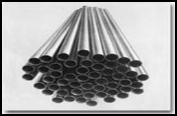

(a) (b)
Figure 2.4: Super-heater
tube may varies widely; (a) Stainless steel tube and (b) ERW boiler tube
Stainless Steel
Tubes:
It is
available in a variety of compositions, most popular of which are ASTM-A-213,
Grade TD-321. (16% Cr, 8%N stabilized with titanium) and ASTM-A-213 Grade
TD-347 (18% Cr, 8% Ni) stabilized with columbium. Either of these two may be
used up to 649°C. Care must be given to choice of welding rod to avoid
brittleness in the welds.
Electric
resistance welded (ERW) Boiler Tubes:
For pipes or tubes size 4 inch (10.2mm) outer diameter and
below, strip is fed into a set of forming rolls which consists of horizontal
and vertical rollers so placed as to gradually from the flat strip in to a tube
which is then allowed to pass the welding electrodes. The electrodes are copper
disks connected to the secondary of a revolving transformer assembly.
The copper disk electrodes make contact on each side of the seam and
temperature is raised to the welding point. Outside flash is removed by a
cutting tool as the tube leaves the electrodes, inside flash is removed either
by an air hammer or by passing a mandrel through the welded tube after the tube
has been cooled. This is termed as Electric Resistance welded or ERW tube/pipe.
If this ERW is being drawn further to get desired size of tubes or pipes, in
cold condition is called as Cold Drawn welded or CDW.
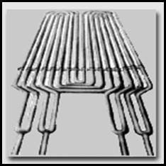
Figure
2.5: various design of super-heater tube (internet reference, 1/2/2005)
CHAPTER 3: RESEARCH MATERIAL AND
METHODOLOGY
3.3
RESEARCH MATERIAL
Material
that was used in my research is a component of a boiler from industry field.
The component is a length of a super-heater tube of boiler and it was given by
Dr. Zainul Huda to me to do the material characterization on it.
The
information of the specimen on physical dimension, application in industries
and common specification of it will be discussed in the following subtopics;
3.3.1
Material physical dimension
The thickness of tube wall = 4.00
mm
The outer radius of tube = 40.00
mm
The inner radius of tube = 32.00
mm
The length of tube = 130.00
mm
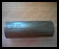
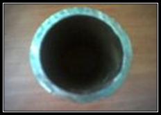
(a) (b)
Figure 3.1: The photo of the specimen on the (a) side and (b)
cross- sectional view.
3.3.2
Material application in industries
This research material was used widely in boiler as the super-heater
tube. This component is very important to make sure the efficiency of boiler
operation is at the high level.
3.3.3
Material common specification
The
super-heater tube material vary widely, with SA-178A and SA-192 used most often
in the lower temperature ranges. SA-210-A1, SA-213-T11, and SA-213-T22 are
commonly seen in the intermediate temperature ranges, with the stainless
grades, most frequently Tp-304H and Tp-347H, reserved for the higher temperature
super heaters, although SA-213-T91 is increasingly specified for the highest
temperatures.
Below
show a table of the common specification of the boiler tubes including
super-heater tube. The table shows the grade, description of the steel, the type
of the tube (either seamless or electric resistant welded, ERW) and the uses of
it.
Table 3.1: Shows the grade,
description of the steel, the type of the tube (either seamless or electric
resistant welded, ERW) and the uses of it (Robert B. Ross, 1968).
|
ASME
Spec.
|
ERW or Smls.
|
Description
|
Typical uses
|
|
SA-178 A
|
ERW
|
Low carbon steel - C=0.18 max.
|
Boiler tubes, economizers, low
temp. superheaters
|
|
SA-192
|
Smls.
|
Low carbon steel - C=0.18 max
|
Waterwalls, economizers, low temp.
superheaters
|
|
SA-210 A1
|
Smls.
|
Medium carbon steel - C=0.27
max.
|
Waterwalls, economizers,
superheaters
|
|
SA
A-210 C
|
Smls.
|
Medium carbon steel - C=0.35
max.
|
Waterwalls, economizers,
superheaters
|
|
SA-209 T1
|
Smls.
|
Low alloy steel - low carbon,
1/2% moly
|
Superheaters
|
|
SA-209T1a
|
Smls.
|
Low alloy steel - medium
carbon, 1/2% moly
|
Superheaters
|
|
SA-209T1b
|
Smls.
|
Low alloy steel - low carbon,
1/2% moly
|
Superheaters
|
|
SA-213
|
Smls.
|
Intermediate alloy - 1/2%
chrome, 1/2% moly
|
Waterwalls, superheaters, not
in common use
|
|
SA-213
|
Smls.
|
Intermediate alloy - 1 1/4%
chrome, 1/2% moly
|
Waterwalls, superheaters
|
|
SA-213
|
Smls.
|
Intermediate alloy - 2 1/4%
chrome, 1% moly
|
Waterwalls, superheaters
|
|
SA-213
|
Smls.
|
Intermediate alloy - 9% chrome,
1% moly, 1/4% vanadium
|
High temperature superheaters -
the latest and greatest
|
|
SA-213
|
Smls.
|
Stainless steel - 18% chrome,
8% nickel
|
Superheaters
|
|
SA-213
|
Smls.
|
Stainless steel for high
temperature service
|
High temperature superheaters
|
|
SA-213
|
Smls.
|
Stainless steel - 16% chrome,
11% nickel
|
Superheaters
|
|
SA-213
|
Smls.
|
Stainless steel for high
temperature service
|
High temperature superheaters
|
|
SA-213
|
Smls.
|
Stainless steel - 17% chrome,
9% nickel, 0.60% titanium
|
Superheaters
|
|
SA-213
|
Smls.
|
Stainless steel for high
temperature service
|
High temperature superheaters
|
|
SA-213
|
Smls.
|
Stainless steel - 17% chrome,
9% nickel, columbium + tantalum=1.00% max.
|
Superheaters
|
|
SA-213
|
Smls.
|
Stainless steel for high
temperature service
|
High temperature superheaters
|
3.2
METHODOLOGY
In
this part, I will try to explain briefly on all equipment that I used in this
research. It is very important to us to know all the principal, steps or
procedure, calculation from data collection and the result that can be used to
observe the characterization of the specimen.
The
description on the operation of the equipment, the advantages why particular
equipment was used also state in this part. The description is all about the
specimen preparation, elemental/ chemical analysis equipment, Hardness testing
equipment, and Microstructural analysis equipment.
I
also include in this chapter the flow of my characterization method that I done
on the specimen to characterize it. The flow is shown in Figure 3.2.


Figure 3.2: Flow of
material characterization method
3.2.1 Surface
preparation of the sample
The
surface preparation of the sample which is cut into the dimension of 10 mm by
10 mm is done. This preparation is needed for the microstructural analysis using
optical microscopy.
The
surface preparation is divided to four main steps which is including mounting,
grinding, polishing and etching (for microstructural analysis only). The theory
and procedure is explained as:
a) Mounting
Mounting
process is needed to meet the requirement of main three important functions (1)
it protects the specimen edge and maintains the integrity of a materials
surface feature (2) fills voids in porous materials and (3) improves handling
of irregular shaped samples. The majority of metallographic specimen mounting
is done by encapsulating the specimen into a compression mounting compound
(thermosets - phenolics, epoxies, diallyl phthalates or thermoplastics -
acrylics), casting into ambient castable mounting resins (acrylic resins, epoxy
resins, and polyester resins), and gluing with a thermoplastic glues.
For metals,
compression mounting is widely used. Phenolics are popular because they are low
cost, whereas the diallyl phthalates and epoxy resins find applications where
edge retention and harder mounts are required. The acrylic compression mounting
compounds are used because they have excellent clarity.
The procedures
to prepare a mounted sample are:
i) Mounting
is done by encapsulating the specimen into a compression mounting compound
(thermosets - phenolics, epoxies, diallyl phthalates or thermoplastics -
acrylics), casting into ambient castable mounting resins (acrylic resins, epoxy
resins, and polyester resins), and gluing with a thermoplastic glues.
ii) The
size of mounting used is 25 mm in diameter.
b) Grinding
Grinding is
required to planarize the specimen and to reduce the damage created by
sectioning. The planar grinding step is accomplished by decreasing the abrasive
grit/ particle size sequentially to obtain surface finishes that are ready for
polishing. Care must be taken to avoid being too abrasive in this step and
actually creating greater specimen damage than produced during cutting (this is
especially true for very brittle materials such as silicon).The machine parameters
which effect the preparation of metallographic specimens includes:
grinding/polishing pressure, relative velocity distribution, and the direction
of grinding/polishing.
For metallic
specimen grinding, sequential grinding with silicon carbide (SiC) abrasive
paper is the most efficient and economical rough grinding process.
In addition to
the correct sequence and abrasive size selection, the grinding parameters such
as grinding direction, load and speed can affect the specimen flatness and the
depth of damage (Richardson, 1974). The basic idea is to remove all of the
previous specimen damage before continuing to the next step while maintaining
planar specimens. The photo that shown the machine for grinding is shown below:
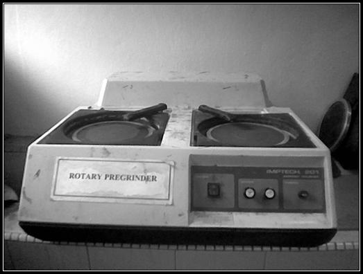
Figure
3.3: Imptech® 201 rotary pregrinder machine at metallurgy lab
The Procedures are:
i) Grinding
process was done by using emery paper. Initially a coarse grade emery paper
(No. 240) is used for this purpose.
ii) The
specimen is gently rubbed backward and forward against it until only scratches
due to this particular paper can be seen to cover the surface.
iii) Then
the specimen is grind on the next finer emery paper in such a direction
that the new set of parallel scratches are at right angles to
the previous set, so that the removal of previous grinding marks is easily
observed. This procedure is repeated till the finest emery paper has been used
(No. 1200).
c) Polishing
The
purpose of final polishing is to remove only surface damage. It should not be
used to remove any damage remaining from cutting and planar grinding. If the
damage from these steps is not complete, the rough polishing step should be
repeated or continued. The procedures are explained as:
i)
The specimen is polished by holding it against a
horizontal rotating disk. The disk is covered with a velvet cloth which has
very fine hard particulars of Al2O3 (~ 600#) embedded in
it.
ii)
During polishing the velvet cloth is supplied with these
particles in form of an aqueous suspension at regular intervals. These abrasive
particles rub against the specimen and produce a very smooth surface. During
this process the surface must attain such a good polish as to resemble a
mirror.
The
picture of the polishing machine is shown as below in figure 3.4
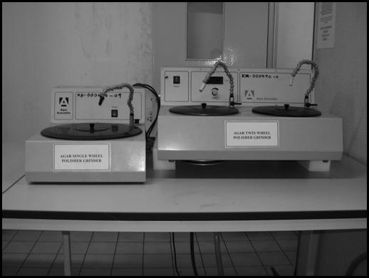
Figure
3.4: Polishing machine
d) Etching (for
microstructural analysis only)
The
purpose of etching is to optically enhance microstructural features such as
grain size and phase features. Etching selectively alters these microstructural
features based on composition, stress, or crystal structure. The most common
technique for etching is selective chemical etching and numerous formulations
have been used. The procedures are explained as:
i) Before
etching, the specimen should be thoroughly washed with water and dried with
alcohol.
ii) The
specimen, with its polished surface up-wards, should be immersed in the etching
solution contained in a small porcelain dish. The etchant reagent that was used
in this method is Nital 2% and it is immersed for 10 seconds.
iii) The
specimen surface should be examined from time to time, and the specimen is
removed from etchant when grain structure is just visible to the unaided eye.
iii)
After etching, the specimen is thoroughly washed with
water and then dried with alcohol.
iv)
Now, the specimen is ready for analysis on microstructural
analysis with optical microscope.
3.2.2 Spark Emission
Spectrometer (SES)
Spark
emission spectrometers also have been used for chemistry analysis in the
sample. Emission spectrometry provides rapid and accurate simultaneous
determination of many elements in metals. This technique has been adopted as
standard method for metal analysis (Internet reference, 13/02/2005). In
steel we can measure the amounts of the alloying elements Cr, Ni, Mo, Ti, V,
impurity levels of S and P and of course we can measure the amount of Fe, C, Mn
and Al using Spark Emission Spectrometer. Elements that cannot be detect with
this spectrometer, such as Cobalt or Tungsten, we can always measure with the
energy dispersive detector on our SEM; but for the application of high
temperature the effect of tungsten and cobalt is not important compared to the
others.
In
this type of spectroscopy, an electrical discharge is generated between an
electrode and the sample, generally in an argon atmosphere. This discharge
removes material from the sample surface ("ablation") and causes
excitation of the constituent atoms of the metallic alloy. The light produced
is split into its component wavelengths, just as a prism separates sunlight
into the colors of the rainbow.
Each
element or type of atom has its own characteristic wavelengths of light.
Therefore, the presence and amount of each element may be determined by the
intensity of light at each wavelength of interest. By measuring the light
intensities for the elements with the use of standards (certified reference
materials), the spectrometer can be calibrated. Thereafter, unknowns may be
measured and the light intensities related directly to chemical concentrations
(Internet reference, 13/02/2005)
In
this graduation exercise, I has used the Spark Emission Spectrometer at
Mechanical Engineering Department Lab and assisted by Mr. Khoo. The model of
the machine is Shimadzu OES-5500II.
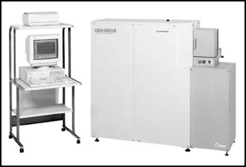
Figure 3.5: Shimadzu®
Spark Emission Spectrometer machine
3.2.3 Optical Microscopy
A
metallurgical microscope is used to reveal details in a material that are too
small to be normally seen with the unaided eye. Of these, optical microscopy is
by far the most important, since the equipment is relatively inexpensive and
the images can be obtained and interpreted easily. The trained observer
looking, for instance, at a price of steel can tell at once whether it was cast
or rolled, and also identify the various phases. Distribution and morphology of
the phases can be studied and, if their properties are known, a quantitative
analysis of the micrographs provides some information about the bulk properties
of the specimen. A limited study of line and surface imperfections is also
possible with the optical microscope.
The
two-dimension surface of a polished and etched specimen exhibits features which
tell something about its three-dimensional microstructure. In order to obtain
reproducible result, with good contrast in the image, the specimen surface is
polished and subsequently etched with appropriate reagents before microscopic
examination. In a polished specimen, the etching not only delineates grain
boundaries, also allows the different phases to be distinguished by differences
in brightness, shape, and color of the grain.
Micro structural examination can provide quantitative information about
the following parameters:
I.
The grain size of specimens.
II.
The amount of interfacial area per unit volume.
III.
In dimensions of constituent phases.
IV.
The amount and distribution of phases. Quantitative
metallographic in involves a large number of measurements, especially if good
precision is required. One is making measurements on random slices through a
three-dimensional object, which may or may not be uniform through-out (Kehl,
G.L, 1949).
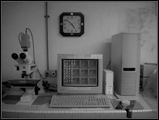
Figure 3.6: Optical
microscopy imaging system at metallurgy lab
The procedures are explained as:
a) The mounted
specimen placed under the microscope lens. Surface leveled with the help of a
leveling device.
b) The microscope is focused until the best
microstructures have seen through the lens. The focusing procedure can be done
by following the focusing procedure as (E.C Subbarao et al., 1972);
i) Initially,
the lowest power objective is used for focusing the specimen.
ii) Turn
the coarse focusing control to lower the body tube until the power low-power
objective is about half a centimeter above the specimen.
iii) Look
through the eyepiece and use the coarse adjustment to raise the objective until
the specimen comes into appropriate focus.
iv) Scan the
specimen and select the area which might warrant more complete study at high
magnification.
v) Raise
the body tube and turn the high-power objective into place.
vi) Watching
the microscope tube carefully from the side of the stage, bring the objective
very close to the specimen. Be sure that the objective lens does not touch the
sample surface at any time. Otherwise the lens may be scratched and permanently
damage.
vii) Raise
the body tube with only fine adjustment until the specimen comes into sharp
focus.
3.2.4 Vickers hardness test
The Vickers hardness test method consists of indenting the
test material with a diamond indenter, in the form of a right pyramid with a
square base and an angle of 136 degrees between opposite faces subjected to a
load of 1 to 100 kgf. The full load is normally applied for 10 to 15 seconds.
The two diagonals of the indentation left in the surface of the material after
removal of the load are measured using a microscope and their average
calculated. The area of the sloping surface of the indentation is calculated.
The Vickers hardness is the quotient obtained by dividing the kgf load by the
square mm area of indentation.
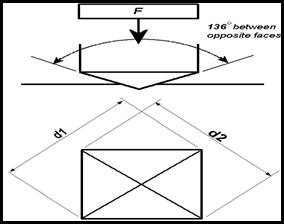
Figure
3.7: Vickers hardness determination of diagonal
F= Load in kgf
d = Arithmetic mean of the two diagonals, d1 and d2 in mm
HV = Vickers hardness
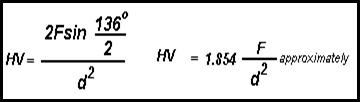
When the mean diagonal
of the indentation has been determined the Vickers hardness may be calculated
from the formula, but is more convenient to use conversion tables. The Vickers
hardness should be reported like 800 HV/10, which means a Vickers hardness of
800, was obtained using a 10 kgf force. Several different loading settings give
practically identical hardness numbers on uniform material, which is much
better than the arbitrary changing of scale with the other hardness testing
methods.
The
advantages of the Vickers hardness test are that extremely accurate readings
can be taken, and just one type of indenter is used for all types of metals and
surface treatments. Although thoroughly adaptable and very precise for testing
the softest and hardest of materials, under varying loads, the Vickers machine
is a floor standing unit that is more expensive than the Brinell or Rockwell
machines (E.C Subbarao et al., 1972).
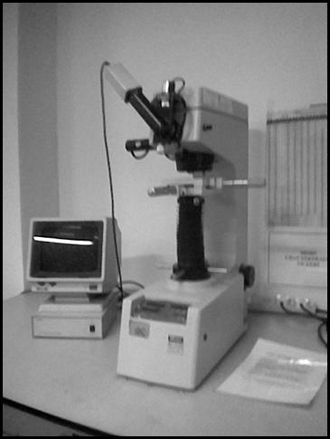
Figure 3.8: Vickers hardness testing machine at material
science lab
There
is some procedure to do this test in a good way and to get good result and it
is explained as:
i)
Load applied in this testing is 10 kgf
ii)
Equipment and TV switch is turn on. The specimen was put
on the equipment bench
iii)
The level adjusted until the TV image is clear
iv)
To make the reading, both two lines need to adjust on the
camera adjuster.
v)
Start button is pushed and after two signal heard, the
image on screen can now be measure on d1 and d2 using the
adjuster and the value is taken from the screen.
vi)
The same procedure was used until 3 readings.
CHAPTER
4: RESULTS AND DISCUSSION
4.1 Result
and discussion of elemental / chemical analysis
Result
of the elemental or chemical analysis for this graduation exercise was obtained
from the Spark Emission Spectrometer machine.
Table 4.1: Percentage
of major alloying element obtained from Spark Emission Spectrometer (SES)
|
Spot
|
Chemical
composition (weight percent, wt %)
|
|
C
|
Si
|
Mn
|
P
|
S
|
Ni
|
Cr
|
Mo
|
V
|
Al
|
|
1
|
0.127
|
0.213
|
0.619
|
0.007
|
0.002
|
0.036
|
0.932
|
0.490
|
0.008
|
0.008
|
|
2
|
0.099
|
0.210
|
0.612
|
0.008
|
0.003
|
0.036
|
0.918
|
0.477
|
0.009
|
0.007
|
|
Average
|
0.113
|
0.211
|
0.615
|
0.008
|
0.003
|
0.036
|
0.925
|
0.484
|
0.008
|
0.008
|
Figure
4.1: Plot of element composition percentage of each element from SES
From
the result of Spark Emission Spectrometer (SES), we can interoperate the properties
of the sample. The percentage of each element, obtained from the result;
especially the core alloying element and the carbide former is very important.
The advantages of this machine makes the analysis is quite good for the most
element except for Tungsten and Cobalt.
As
mentioned in chapter 3, Emission spectrometry provides rapid and accurate
simultaneous determination of many elements in metals. This technique has been
adopted as standard method for metal analysis.
If
we go through the result of the sample, we can see there are ten elements were
detected by this machine correctly. The original copy of the result is shown in
Appendix A-I. Here I will discuss on three major element presented in the
result basis on the percentage of it affected the properties of the sample when
it is used at the high temperature one by one. The elements are carbon,
chromium and molybdenum.
Carbon-0.113%
The
percentage of carbon content which is in average of 0.113% for this sample
shows the sample is in the group of the low carbon steel. As we know, carbon is
the carbide former. The presence in the low percentage is not a big problem if
it is assisted by the alloying element like chromium which is also a carbide
former.
The
low percentage of carbon content gives the material low in the hardness
properties. Thermal treatment may require improving the hardness properties. A
high degree of ductility is the advantage of this type steel.
Assisted
by other alloying element, will help this group of steel to be used at higher
temperature, say around 550°C to 700°C (L. Colombier & J. Hochmann,
1965).
Chromium-
0.925%
Chromium
forms stable carbides with available carbon (0.113%), the carbon combining with
the chromium in preference to iron. These are harder that carbon carbide and
more sluggish in their metallurgical reaction, thus longer the time at high
temperature.
Chromium
also imparts the corrosion resistance as any chromium at the steel surface
becomes oxidized and this improved resistance to rusting.
Being
a carbide former, chromium also aids carburization. With the percentage of
0.925% (~1.00%), the chromium content in this sample is enough to affected the
properties of the tube and it is suitable for the operation in the high
pressure, high temperature (below than 650°C), and also in corrosive
condition in a boiler.
Molybdenum-
0.484%
Molybdenum
is the most popular alloying element added to increase the creep strength.
Molybdenum is also a carbide former, the resultant carbide being distributed,
small and very stable. Thus it gives good grained steels, improved the hot
strength and creep strength of the material, increase the depth of hardness
achieved and improved the fatigue strength.
The
percentage of 0.484% of molybdenum is just enough to help this sample to be
used in the condition like in a boiler which is the creep strength is needed.
4.2
Result and discussion of Hardness testing
|
Readings
|
Diagonal
|
VHN
|
|
D1
|
D2
|
|
Reading 1
|
317.8
|
320.7
|
182
|
|
Reading 2
|
320.6
|
319.3
|
181
|
|
Reading 3
|
321.4
|
3.8.5
|
181
|
|
Average
|
|
|
181.3
|
Table 4.2: Result of hardness test
The
value of Vickers hardness test obtained from the experiment is 181.3 HV/10. The
value is a little bit higher that the value of the normal low carbon steel
which is lowers that 150 HV.
The
hardness value is higher because of the heat treatments that maybe have been
done in the production of this component.
Actually,
the property of the hardness is the effects of the composition of the element
in the steel. With the value of hardness is not too high, the ability to
be fabricated to desired shapes will increase. So, the more complex design will
be done to reach the requirement and against the failure at the temperature as
high as 550°C
4.3
Result and discussion of Microstructural analysis
(a) (b)
(c) (d)
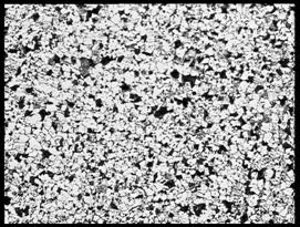
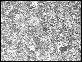
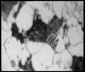
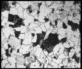
Figure 4.2: The
optical micrograph of sample under various magnifications (a) 100X, (b) 200X, (c)
500X and (d) 1000X

Figure 4.3: Intercept Method for grain size calculation
Calculation of optical micrograph line scale for 500 X
Length of line after magnification, L1 Actual
length, Lo
76.00
mm = 0.1
mm = 100 μm
7.6
mm =
0.01 mm = 10.0 μm
So, 15.2 mm =
= 20.0μm
Grain size calculation;
Grain size, d = Lo Lo
= Real length of line
n
n = Counted number of grain boundary intercepted on line
i) Line A; L1
= 115.3 mm so, Lo =
151.57μm. n = 10
d
= 151.57
10
= 15.157 μm
ii) Line B; L1 = 149 mm so,
Lo = 196.0 μm. n = 13
d
= 196.00
13
= 15.08 μm
ii) Line C; L1 = 149 mm so,
Lo = 196.0 μm. n = 14
d
= 196.00
14
= 14.00 μm
Average = 15.157 μm +
15.08 μm + 14.00 μm
3
= 14.745 μm
The
microstructure of high temperature resistant low carbon steel are consists of
ferrite mainly and some regions containing a mixture of pearlite, bainite and
martensite. All the microstructure shows in the result is actually
at the same spot, but at difference magnification. For the magnification of 100
X, we can see that the grain is fine ferrite with region of transformed
structure.
With
the higher magnification of 200 X, we can see the ferrite and region of
bainite. The picture of magnification 500 X shows that the ferrite and bainite
clearly (Verlog Staheleisen m.b.H, 1966). With magnification of 1000 X, we can
see that the addition to ferrite, coarse and fine bainite is presents.
From
the calculation of grain size, we have the value of grain size are 14.745
μm in average. The sizes of grain size are actually will affect the
yield strength of the material in the operation condition. Clearly, we
know the relation of the size of the ferrite (single phase solid solution)
assisted by pearlite as shown in the optical micrograph, the principle of the
yield strength relationship due to grain size will be shown as:
σys
= σi + ky d-1/2 ----------------(4.1)
Which; σi
= Resistance of lattice to dislocation movement
ky
= Constant value
d
= grain size
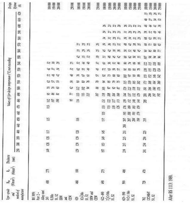
The values of
σi and ky are found to vary with alloy content and
microstructure as in this research which is in group of low alloy steel 1Cr1/2Mo,
the various of design stress value (f) regarding to the various
operating temperature up to 620°C (as in the appendix A.3). This table is
from BS 3059(Steel boiler and super heater tube).
As
stated in equation 4.1, we can say clearly, if we have the smaller grain size,
the higher the yield strength can be obtained. For this sample, we can see that
it is can be use in operation temperature from 490°C at 113 MPa design
stresses up to 570°C at 22 MPa design stresses. The influence of grain size
on yield strength in ferritic steel is presented as in figure 4.3. (Richard W.
Hertzberg)
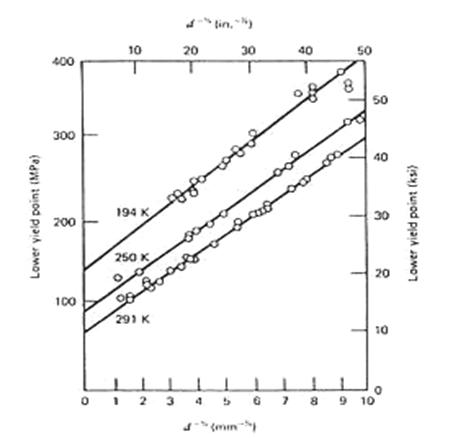
Figure
4.4: The influence of grain size on yield strength in ferritic steel (Richard
W. Hertzberg)
CHAPTER 5: CONCLUSION AND
RECOMMENDATIONS
5.1 Conclusion
The
main point to conclude after all the testing and analysis were done is that
this component is actually in the group of low-alloy or martensitic steel in a
group of 1/2Cr.1/2Mo steels.
As
we see the percentage of carbon which is low, the percentage of Chromium and
molybdenum, we can say that the presences of those alloying element is very
important to give the component a good creep strength and some corrosion
resistance.
The
value of hardness gives the material to have a good workability to make sure
the various design can be made to give the boiler more efficient and lower the
risk of failure.
The
presence of stable, fine and hard carbide from the carbide former like chromium
and molybdenum in the micrograph in figure 4.2 will help to prevent the grain
growth of the material and obstruct the dislocation.
The
grain size of this material are also fine enough to give the good yield
strength up to design stresses of 113 MPa at 490°C and 570°C at 22 MPa
stresses.
As
the overall conclusion, we can say that this component (the sample in this
research) is just suitable to be use in the high temperature condition of
490°C to 570°C regarding to the properties of low hardness value, low
chromium content and the dispersion of carbide which is not too fine.
5.2 Recommendations
Some
recommendations can be made to improve the properties of this component to make
it more suitable to use in a boiler in the longer life without fail. The aspect
that is very important to look forward is the percentage of the alloying
element, the heat treatment and good corrosion protection that can be done to
increase the creep strength, resistant to oxide, corrosion resistance, good
weldability and formability to shape.
The
heat treatment which is suitable to increase the properties of this sample is
the same as the low carbon alloy steel heat treatment. The heat treatment like
heated at the temperature of 880°C - 900°C for 30 minutes, then cooling
to 650°C for one hour and repeated at least once will increase the
properties. This result the small globules or sphere of carbides that will
obstruct dislocation in the ferritic matrix.
A
good corrosion protection was needed to improve the properties of the material
which is used in the high corrosion environment. As we know, corrosion is
caused by the action of oxygen and moisture on irons, forming a bulky, loosely
adherent mixture of oxides. The selections of good permanent corrosion
protection like phosphate or chromate treatment coat the steel surface with a
film which has corrosion resisting properties.
The
properties of the component were also depends on the carbon content. The higher
the carbon content will also increase the ability of the material to form
carbide when the higher percentages of carbide former like chromium presence.
As the example, the austenitic steel with the chromium content in the range of
11% - 25% and also the greatest and the latest super heater tube is ASTM A 213
which is the Intermediate alloy with 9% chrome, 1% moly, 1/4% vanadium will be
used as the super-heater tube at the more higher temperature as mentioned in
the beginning of this report.
The
process properties are also very important and it can be reached by adding the
element like sulphur in proper amount without changing the properties of the
steel.
In
overall, recommendation is just a recommendation, the first thing to think
before any technique of treatment or selection of alloying elements components
to use is where the steel to be use is. The suitability of cost, output
efficiency, temperature, and the fuel, pressure of the boiler and life of
material are need in a big consideration.
APPENDIX

APPENDIX A
A.1 printed result from
Shimadzu machine (Compositional analysis)

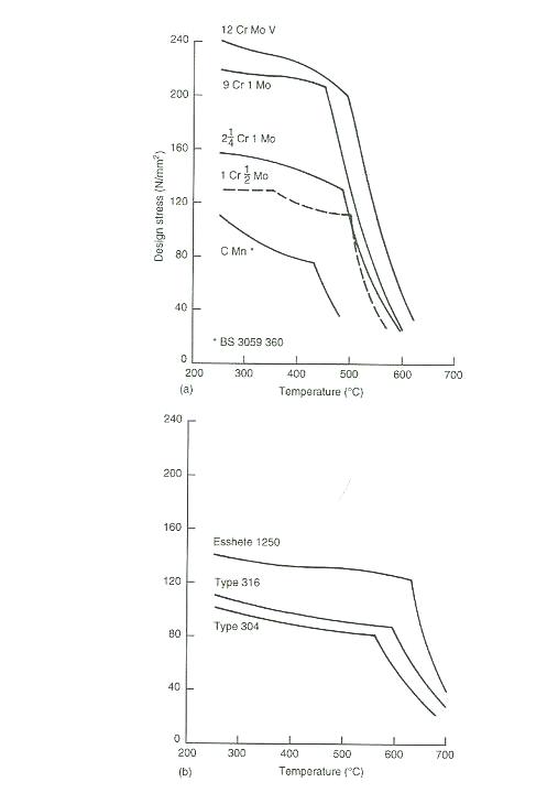
A.2 The Effect of alloying element on design stresses
and application temperature.
A.3 various of design stress
value (f) regarding to the various operating temperature .This
table is from BS 3059(Steel boiler and super heater tube).
A.4 Scalling for optical micrograph
76
mm = 0.1mm = 100 μm
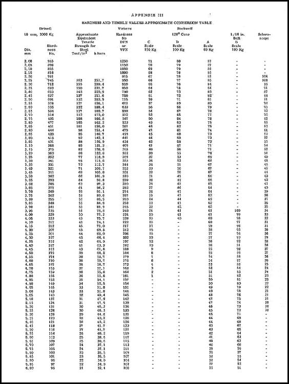
APPENDIX C
C.1 Temperature conversion
table

C. 2 Hardness and tensile
conversion table